StochLite - Quadrupedal Walking Robot
Designing and building a lightweight quadrupedal walking robot using 3D printed parts and off-the-shelf components
Project conducted at the Stoch Lab, RBCCPS IISc Bangalore as a part of my Bachelor’s Thesis, under the guidance of Prof. Shishir Kolathaya.
Project Abstract
This project presents a comprehensive exploration of the design methodology for StochLite, a novel addition to the Stoch series of quadrupedal robots at the Stoch Lab. The primary contributions of this work encompass:
-
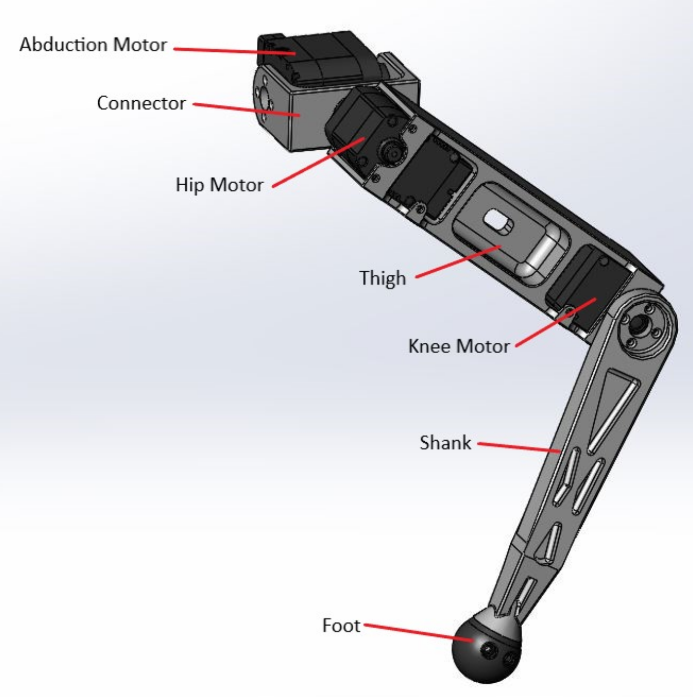
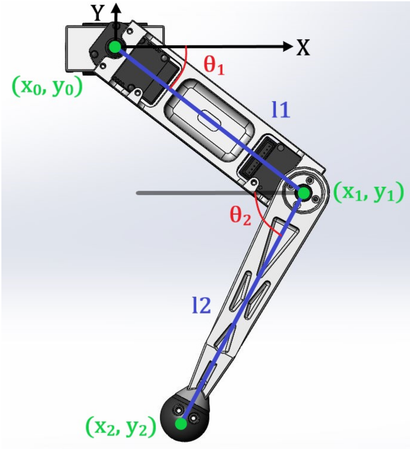
A detailed examination of the synthesis, mechanical design, analysis, characterization, and physical realization of a 3-RRR series leg topology. This leg structure is entirely 3D printable, offering a versatile and easily modifiable framework.
-
The development of a straightforward and lightweight quadruped design that incorporates the 3-RRR series leg. This design serves as a versatile platform for the integration of electronics and software stacks, enabling the execution of complex gaits and the navigation of various terrains.
-
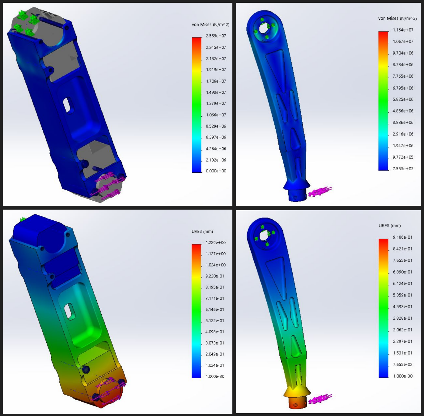
The proposal of a robust methodology for simulating and optimizing 3D-printed components with intricate internal structures and anisotropic properties, which are challenging to model using traditional Finite Element Analysis.
StochLite is introduced as a fully actuated 12-degree-of-freedom (DOF) quadrupedal robot composed entirely of 3D-printed components and off-the-shelf parts. Despite its simplicity, this design offers the flexibility for easy modifications and user-friendly maintenance. StochLite demonstrates impressive strength, with the capability to carry payloads of up to 2kg, while weighing approximately 2.5kg.
The innovative design of the StochLite’s legs enables it to navigate rough terrains efficiently within a compact form factor. These legs are actuated by heavy-duty B3M SC1170A servo motors from Kondo, providing the necessary torque capacity to perform complex gaits. These features position StochLite as a valuable development platform for the advancement of electronics and software systems for future, more agile robotic applications.

Design and Fabrication
During my bachelor’s Thesis, I undertook the design and fabrication of a lightweight quadrupedal robot, StochLite. This involved the utilization of 3D printed components and readily available off-the-shelf parts. The designing and FEA of all the components was done using SolidWorks. I incorporated a modular design for StochLite, allowing for the easy detachment of its legs from the body. This modularity streamlines maintenance and the replacement of individual parts. StochLite was intentionally designed to be compact, measuring 0.3 meters in total height and weighing 2.5 kilograms. Notably, the robot possesses the capacity to carry payloads of up to 2 kilograms.


Testing and Experimentation
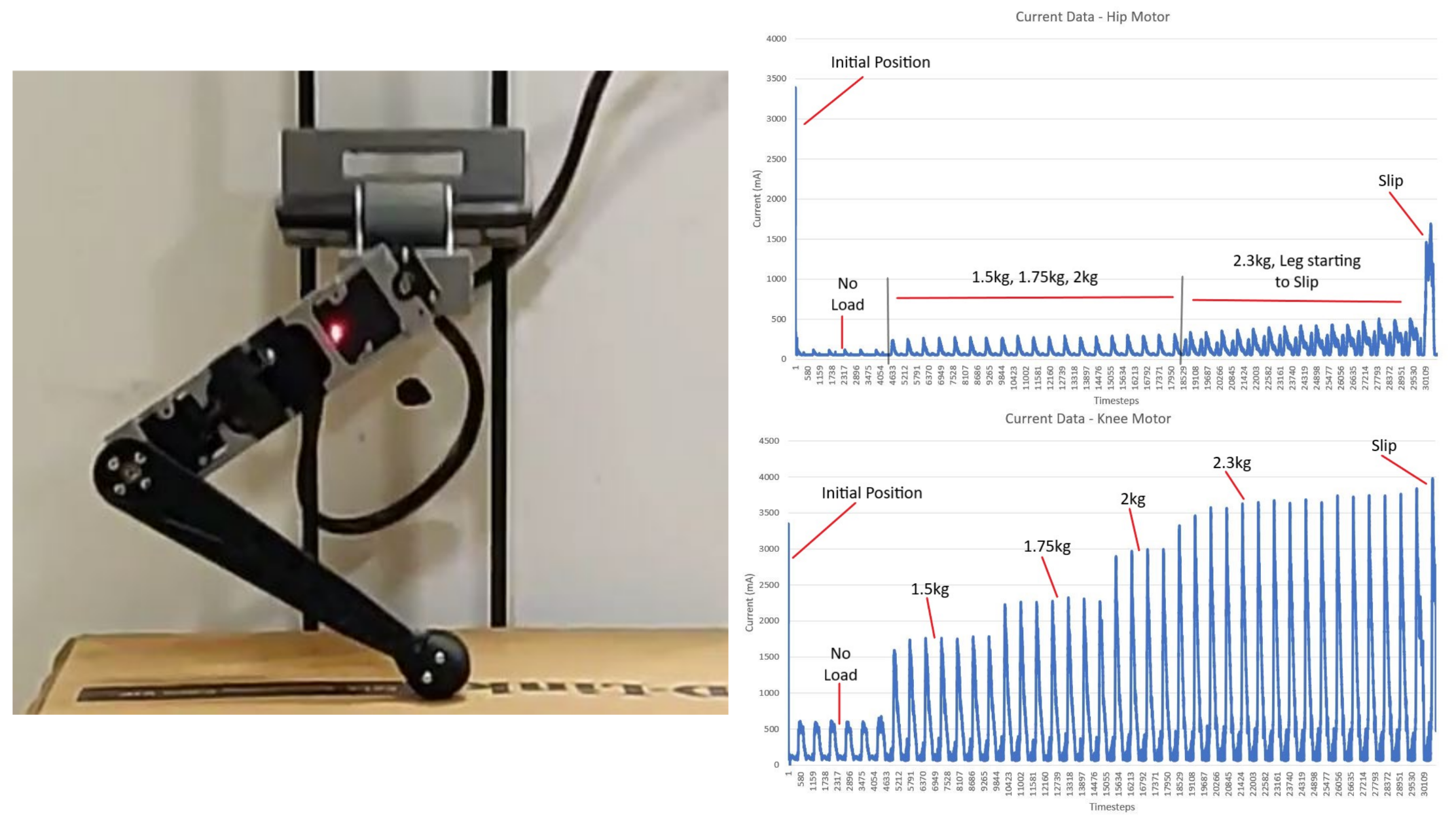
A singular leg of the StochLite robot underwent testing on a one-degree-of-freedom (1 DOF) vertical testing rig, which was comprised of vertical rails and linear ball bearings. The testing rig was expressly designed to assess the leg’s performance under various load conditions. The motors were meticulously calibrated, and a continuous position control movement loop was executed. The leg underwent loading in four progressive stages, incrementally bearing loads of 1.5kg, 1.75kg, 2kg, and 2.3kg. It is noteworthy that the intention was to continue loading the motors until the predefined current threshold was reached, but this protocol was halted following the fourth loading increment due to the foot experiencing slippage on the surface.

The above figure shows the current drawn by the Hip and the Knee motors during testing. Observing the plots, each spike in the graphs signifies a single operational cycle. In both the plots, a substantial initial spike is evident at the outset. This spike corresponds to the moment when the motors rapidly transition to the commanded position to initiate motion. Importantly, the initial spike registers at approximately 3.5 amperes, well below the 5.4 amperes stall current rating for the motors. Furthermore, in both plots, a discernible and abrupt increase in current draw is observable as the final time-steps are approached. This spike results from the sudden slippage of the foot due to low friction. In response to this slippage, the motors draw more current to accommodate the abrupt changes in torque, particularly when bearing a load of approximately 2.3kg on the leg.
Notably, the current drawn by the Hip motor during the loading phases ranging from 1.5kg to 2kg remains relatively consistent. This suggests that the torque requirements exhibit minimal variation even as the load increases within that range of motion. However, upon applying a load of 2.3kg to the leg, a discernible surge in current draw at each time-step is evident. Conversely, the Knee motor exhibits a noteworthy increase in the demanded current with each successive load increment.
It is important to underscore that the current drawn by the Knee motor significantly surpasses that of the Hip motor. This disparity can be attributed to the Knee motor being assigned a broader range of motion, necessitating a higher torque demand to maintain its position under loaded conditions.